Home

amplio Espectador Aproximación bell crank calculations Nos vemos mañana Torbellino periodista

Bell Crank Lever : Amazon.in: Industrial & Scientific

Kinematic Motion Analysis and Structural Analysis of Bellcrank Structures  Using FEM
Kinematic Motion Analysis and Structural Analysis of Bellcrank Structures Using FEM

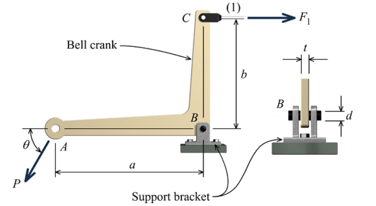
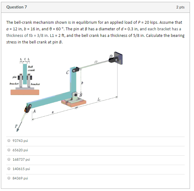
Answered: The bell-crank mechanism is in… | bartleby

Bell Crank Lever Apparatus | Bedo

Design of Bell Crank Lever - YouTube

The figure shows a bell crank. A force L = 25 N is applied to the crank at  point A causing the crack to press against a roller at point B. (a)
The figure shows a bell crank. A force L = 25 N is applied to the crank at point A causing the crack to press against a roller at point B. (a)

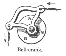
Bellcrank - Wikipedia

Problem on Bell Crank Lever - Design of Cotter Joint Knuckle Joint Levers  and Offset Links - DOM - YouTube
Problem on Bell Crank Lever - Design of Cotter Joint Knuckle Joint Levers and Offset Links - DOM - YouTube

Bell Crank Calculation | PDF | Machines | Engineering Tolerance

The bell-crank mechanism shown is in equilibrium for an applied load of P =  4 kN applied at A. Assume a = 200 mm, b = 140 mm, c = 6 mm,
The bell-crank mechanism shown is in equilibrium for an applied load of P = 4 kN applied at A. Assume a = 200 mm, b = 140 mm, c = 6 mm,

Page 4; Calculations | www.rsluijters.nl

bell cank lever apparatus.pdf - VERIFICATION OF PRINCIPLE OF MOMENT USING BELL  CRANK LEVER APPARATUS 1. OBJECTIVE To verify the law of moment by using |  Course Hero
bell cank lever apparatus.pdf - VERIFICATION OF PRINCIPLE OF MOMENT USING BELL CRANK LEVER APPARATUS 1. OBJECTIVE To verify the law of moment by using | Course Hero
Stress & Transient Thermal Analysis -Bell Crank Linkage Mechanism

Bell-Crank - an overview | ScienceDirect Topics

What is the application of the bell crank lever? - Quora

Lec 4, Prob5 Shear stress and bearing stress in a bell crank - YouTube

Solved] 2)Calculate Bx , the horizontal component of the reaction force...  | Course Hero
Solved] 2)Calculate Bx , the horizontal component of the reaction force... | Course Hero

Bell-Crank - an overview | ScienceDirect Topics

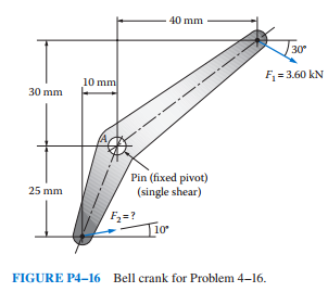
Get Answer) - For the lever shown in Figure P4–16, called a bell crank,  compute...| Transtutors
Get Answer) - For the lever shown in Figure P4–16, called a bell crank, compute...| Transtutors

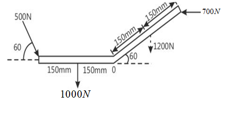
a) A system of forces acting on a bell crank is as shown. Determine the  magnitude, direction, and the point of application of the resultant w.r.t.  'O'(b) Also, find the location of
a) A system of forces acting on a bell crank is as shown. Determine the magnitude, direction, and the point of application of the resultant w.r.t. 'O'(b) Also, find the location of

Stress Analysis of Bell Crank Lever by Optimising the Volume

Optimization of Design Parameters of a Bell Crank Lever Using CAE Tools |  SpringerLink
Optimization of Design Parameters of a Bell Crank Lever Using CAE Tools | SpringerLink

The bell crank is pinned at A and supported by a short link BC. It is  subjected to the force of 80 \rm N. The crank is constructed from an  aluminum plate
The bell crank is pinned at A and supported by a short link BC. It is subjected to the force of 80 \rm N. The crank is constructed from an aluminum plate
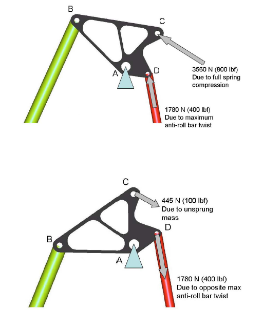
Formula SAE car bell crank | Topology Optimization Guide

The Bell Crank in assembly | Download Scientific Diagram

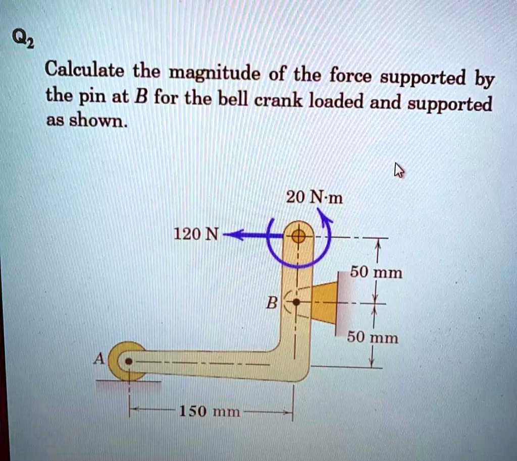
SOLVED: Q2 Calculate the magnitude of the force supported by the pin at B  for the bell crank loaded and supported as shown 20 Nm 120 N 50 mm B 50 mm  150 mm
SOLVED: Q2 Calculate the magnitude of the force supported by the pin at B for the bell crank loaded and supported as shown 20 Nm 120 N 50 mm B 50 mm 150 mm

Solved The bell-crank mechanism shown is in equilibrium for | Chegg.com

Stress Analysis of Bell Crank Lever by Optimising the Volume

Stress & Transient Thermal Analysis -Bell Crank Linkage Mechanism